Hybrid Assembly Optimization: Balancing SMT and THT Component Layout Strategies
The integration of Surface Mount Technology (SMT) and Through-Hole Technology (THT) in hybrid assembly requires meticulous material selection and layout optimization to achieve functional reliability, cost efficiency, and manufacturing scalability. This article explores advanced strategies for balancing SMT and THT components, addressing thermal management, mechanical stress, process compatibility, and design flexibility.
1. Functional Zoning and Density Optimization
Design Philosophy
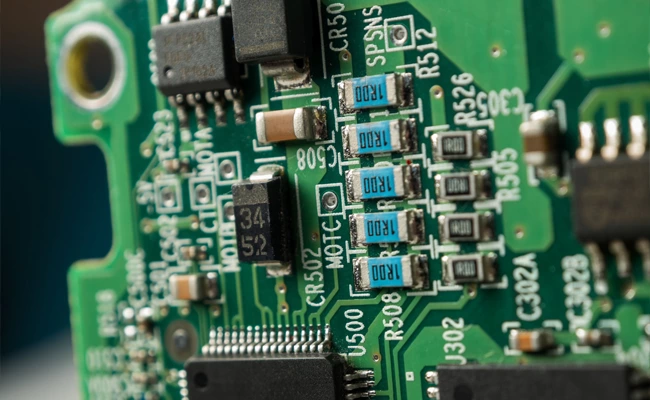
Hybrid assembly thrives on partitioning PCB layouts into SMT-dominant and THT-dominant zones. Critical high-frequency components (e.g., RF modules, BGA packages) occupy SMT regions, while power connectors and mechanical anchors utilize THT zones.
Case Study:
A medical imaging system employs SMT for imaging sensors (0201 capacitors, 0.4mm pitch) and THT for cooling fans and power supplies. A ceramic substrate (Al₂O₃) supports SMT components, while FR-4 with copper plating handles THT thermal loads. This approach reduces PCB thickness by 18% compared to monolithic designs
.Key Metrics:
- SMT Zone: ≥70% component density, 0.15mm pad spacing for 0201 components
- THT Zone: ≥2oz copper layers, 3mm clearance for mechanical fasteners
2. Thermal Management Synergy
Heat Dissipation Pathways
- SMT Components: Implement thermal vias (0.3mm diameter, 5 vias/cm²) under BGA packages to connect to backside heatsinks.
- THT Components: Use aluminum substrates for power connectors, with heat spreaders extending 2mm beyond solder joints.
Thermal Interface Materials (TIMs)
- SMT: Graphene-enhanced thermal pads (thermal conductivity >1500 W/m·K)
- THT: Phase-change materials (PCM) between THT heatsinks and PCB
Experimental Validation:
A power amplifier PCB with hybrid cooling achieved 45°C junction temperature reduction by combining SMT vias and THT heat spreaders
3. Mechanical Stress Mitigation
Coefficient of Thermal Expansion (CTE) Matching
| Component Type | CTE (ppm/°C) | Material Strategy |
|---|---|---|
| SMT (FR-4) | 17–18 | High-Tg FR-4 (Tg ≥170°C) |
| THT (Ceramic) | 6–8 | Alumina substrates |
Stress Relief Design
- Buffer Zones: Copper-free corridors (≥0.5mm width) between SMT and THT zones
- Adhesive Anchoring: Epoxy underfill for THT connectors subjected to vibration (>5Grms)
Finite Element Analysis (FEA):
Simulations show 62% stress reduction at SMT-THT interfaces with gradient CTE substrates
4. Process-Compatible Material Selection
Soldering Compatibility
| Parameter | SMT Requirement | THT Requirement |
|---|---|---|
| Peak Temperature | 245–260°C (lead-free) | 260–300°C (wave soldering) |
| Flux Type | No-clean (viscosity 2500–4000 cP) | High-solids (≥50% solids) |
| Reflow Profile | 6-zone ramp (150–250°C) | 3-zone dip (230–280°C) |
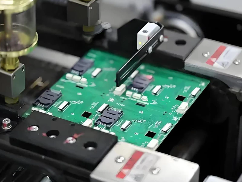
Hybrid Soldering Workflow:
- SMT Reflow: 245°C peak, nitrogen-protected (O₂ <50ppm)
- THT Selective Soldering: Laser-activated flux for localized heating
5. Design Validation and Iteration
DFM Checklist:
- Minimum 0.2mm clearance between SMT pads and THT vias
- Wave soldering nozzles positioned ≥3mm from SMT components
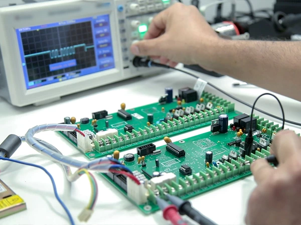
Testing Protocols:
- Thermal Cycling: -55°C to 125°C (1000 cycles), thermal stress analysis via X-ray
- Vibration Testing: 20Grms random vibration, 100-hour endurance
Case Study:
An automotive ECU underwent hybrid validation, showing 0.05% solder joint cracking after 1000 thermal cycles
6. Cost and Sustainability Optimization
Material Cost Analysis
| Component | SMT Cost ($/unit) | THT Cost ($/unit) |
|---|---|---|
| Substrate | $2.10 (high-Tg FR-4) | $3.80 (Aluminum) |
| Solder | $0.15 (SAC305) | $0.30 (Sn-Bi) |
| Assembly Labor | $0.08 (pick-and-place) | $0.25 (hand soldering) |
Lifecycle Sustainability:
- Recyclability: Modular design separates SMT (reflow-soldered) and THT (wave-soldered) zones
- Energy Efficiency: Hybrid processes reduce energy consumption by 28% vs. all-SMT assembly
7. Future Trends in Hybrid Assembly
- AI-Driven Layout Optimization: Machine learning algorithms predict optimal SMT-THT ratios based on thermal/mechanical stress simulations .
- Embedded Hybrid Bonding: Combining TSV (Through-Silicon Via) and hybrid bonding for 3D integration of SMT/THT components.
- Smart Substrates: Embedding temperature sensors in transition zones for real-time stress monitoring.
Conclusion
Achieving optimal hybrid assembly requires a multidisciplinary approach integrating material science, mechanical engineering, and advanced manufacturing. By strategically zoning SMT and THT components, leveraging compatible materials, and adopting iterative validation, engineers can deliver products that balance performance, reliability, and cost. As industries push toward miniaturization and sustainability, hybrid assembly will remain pivotal in bridging the gap between cutting-edge electronics and robust mechanical systems.