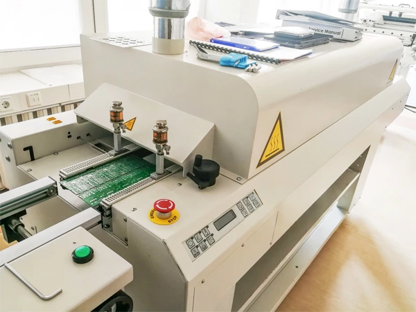
What are the differences between SMT and through-hole assembly in terms of material selection?
Publish Time:
The differences between SMT (surface mount technology) and THT (through-hole technology) in terms of material selection are mainly reflected in solder, substrate materials, flux, and packaging design.
1. Solder Selection
| Aspect | SMT | Through-Hole Assembly (THT) |
|---|---|---|
| Solder Form | Paste (semi-liquid with metal particles and flux) | Preforms, solder wire, or solder paste (higher metal content required) |
| Alloy Composition | Commonly Sn-Pb (e.g., Sn63/Pb37) or lead-free (e.g., SAC305) | High-temperature alloys (e.g., Sn-Bi, Sn-Ag-Cu-Bi) with melting points >230°C |
| Application | Low-melting solder paste (183°C eutectic point) for rapid reflow | High-temperature solder (e.g., 260°C+) for durability |
| Special Processes | Requires paste with high thixotropy for stencil printing | Wave soldering or selective soldering demands fluid flux viscosity |
2. Substrate Materials
| Aspect | SMT | Through-Hole Assembly (THT) |
|---|---|---|
| Primary Materials | FR-4 (epoxy-glass), focusing on high-density routing and microvias | Ceramic (Al₂O₃), high-Tg FR-4, or metallized substrates (e.g., nickel-gold plating) |
| Thermal Performance | Tg ≥170°C to match reflow profiles | Tg ≥200°C and low CTE to resist thermal warping |
| Hole Design | Laser-drilled microvias (0.1–0.3mm) | Mechanical drilling (0.5–1.5mm) with plated through-holes (PTH) |
3. Flux and Process Compatibility
| Aspect | SMT | Through-Hole Assembly (THT) |
|---|---|---|
| Flux Type | Water-soluble or no-clean flux (low residue) | High-activity flux for oxidation resistance during wave soldering |
| Process Requirements | Precision stencil printing and reflow profile control | Additional steps (flux activation, wave soldering) |
4. Packaging and Component Design
| Aspect | SMT | Through-Hole Assembly (THT) |
|---|---|---|
| Component Packaging | Leadless or short-lead (e.g., QFP, BGA) with tight pitch (≤0.4mm) | Long leads (e.g., DIP connectors) requiring coplanarity checks |
| Thermal Stress | Components must tolerate 260°C reflow (e.g., EMC, LCP materials) | Components rated for >300°C (e.g., PPS, PCT) |
| Design Rules | Minimized pad spacing (0.15mm for 0201 components) | Larger pad spacing (≥1mm) to accommodate lead bending |
5. Additional Key Differences
- Board Thickness:
SMT favors thin boards (1.6–2.0mm), while THT requires thicker substrates (≥2.4mm) for mechanical stability. - Plating Processes:
SMT uses ENIG (Electroless Nickel Immersion Gold) for solderability; THT relies on through-hole plating (PTH) for conductivity. - Regulatory Compliance:
SMT prioritizes RoHS (lead-free) and REACH (low SVHC), while THT may still use Sn-Pb alloys in cost-sensitive markets.
Typical Applications
| Scenario | SMT | Through-Hole Assembly (THT) |
|---|---|---|
| Consumer Electronics | Smartphones, wearables (thin, lightweight) | Power adapters, connectors (high current) |
| Industrial Systems | PLCs, sensors (high-frequency, compact) | Relays, circuit breakers (vibration resistance) |
| Automotive | ECU, BMS (reliability under thermal cycling) | Ignition systems, wiring harnesses (durability) |
Hybrid Solutions
A blended approach is common:
- SMT for RF modules (miniaturization)
- THT for power connectors (thermal/mechanical stability)
Conclusion
The choice between SMT and THT hinges on:
- Density vs. Durability: SMT for miniaturization, THT for robustness.
- Thermal Requirements: SMT handles high-density heat dissipation; THT excels in high-temperature environments.
- Cost Efficiency: SMT lowers production costs at scale, while THT suits low-volume, high-reliability needs.
For mission-critical applications (e.g., aerospace), combining both technologies ensures optimal performance and reliability.
References:
- IPC-A-610G (Acceptability of Electronic Assemblies)
- TNEMS Hybrid Assembly Whitepaper (2025)
